Contents
Introduction to Digital Modes
In amateur radio, alongside voice and CW (Morse), there are many digital operating modes. Some of these use the internet (such as EchoLink and DMR), but this guide will focus on the RF specific digital modes. In these modes, a computer is connected to the radio, and while a signal is still transmitted over the air with no assistance from the internet, the signal is encoded. This can be very useful for amateur radio operators as the narrow bandwidth required means that the signal can be decoded at a much weaker Signal to Noise Ratio (SNR) than a voice signal. Because of this, DX can be sought even when the bands are closed to voice. This article will explain everything you need to know about FT8/FT4 and how to configure software to enable you to use this useful mode.
Why use FT8/FT4?
FT8/FT4 are very powerful modes of transmission, and enable you to make contact with stations even when the conditions are too poor to make a voice contact. They are very useful for hunting awards, both for specific countries/prefixes and for awards such as DXCC (DX Century Club), IOTA (Islands on the Air) and POTA (Parks on the Air).
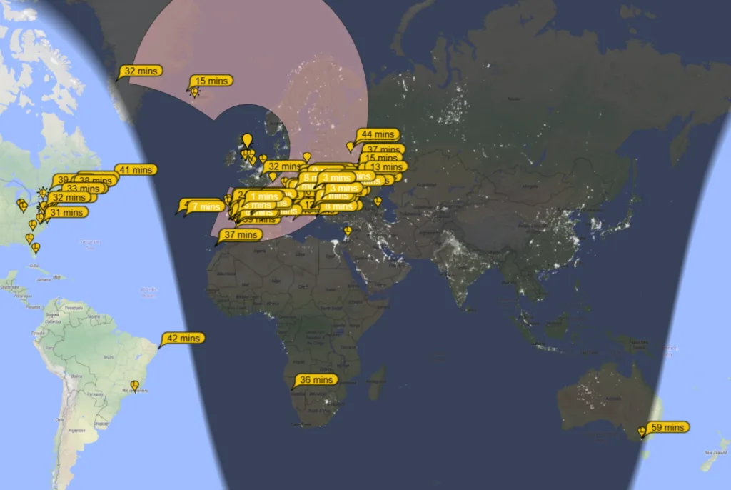
A major benefit of digital modes such as FT8 and FT4 is the almost instant statistics generated by your transmission. As soon as you transmit on these modes, other stations who receive your signal will automatically “report” you. The main website to view these spots is PSK Reporter (link opens in new tab). After transmitting, you can search your callsign and see “pins” of every station that has heard you, view their station QTH and information and your signal report. This is anextremely useful feature as you can see whether a band is open and test antenna configuration.
Another useful feature of the FT8/FT4 software (such as JTDX and WSJTX – more on this later!) is the ability to automatically log QSOs as they happen. I will cover this in later sections of this article.
An additional service you can use for cluster spot handling/signal report data is the Hamalert website (link opens in new tab). Using this free service, you can receive mobile app notifications whenever your callsign is “spotted” on the cluster following an FT8/FT4 transmission. You can also enable this to be broadcasted via Telnet, meaning you can receive these spots directly inside your logging software suite.
Understanding FT8/FT4 – The Basics
FT8 is a mode designed by Joe Taylor K1JT and Steve Franke K9AN. It was developed as a weak signal communication mode useful when band conditions are poor.
FT8 operates in 15 second “blocks”. Station A will transmit for 12.6 seconds, your station will decode this in 2.36 seconds, and then your station (station B) will transmit for 12.6 seconds and station A will decode for 2.36 seconds. The full process of two messages between two stations will take 30 seconds in total. Although this sounds complicated, the software will handle the majority of this transmission automatically.
FT4 is a similar mode but runs in 7.5 second transmissions, meaning that a QSO can be completed in a shorter total time although leaves less room for error and QSB (meaning it is more useful for stronger signals).
FT8/FT4 transmissions run in a standard sequence, as follows:
- (message 1) Station A will call CQ with a message such as “CQ M7OJA IO94”.
- (message 2) Station B will reply to the CQ with a message such as “M7OJA M7XXX IO91”.
- (message 3) If station A hears the message, they will reply with a signal report such as “M7XXX M7OJA -13”.
- (message 4) Station B will then reply to confirm receipt of signal report and provide theirs, such as “M7OJA M7XXX R-18”.
- (message 5) Station A will then call 73 such as “M7XXX M7OJA RR73”.
- (message 6) Station B will then end the QSO such as “M7OJA M7XXX 73”.
The information transmitted here is translated to:
M7OJA (IO94) receives M7XXX (IO91) with a signal report of -13.
M7XXX (IO91) receives M7OJA (IO94) with a signal report of -18.
QSOs nearly always follow this format, although there is an option to omit the grid square transmission (message 1) in order to complete the QSO quicker.
In the event of QSB or any reason why your message was not received, your software will automatically repeat the message until the operator at either end chooses to call CQ again. Some stations are more patient than others, ranging from a few repeat messages to on occasion as many as 20. In QSO with a station in Brazil, it took around 30 messages for the QSO to finish. Once you choose a station to reply to/someone replies to your CQ, the software will automatically handle the sequencing of messages and repeat as needed until the QSO is complete.
Signal reports in FT8/FT4 range from -25 to +25, and they are the Signal to Noise Ratio (SNR) of the transmission. These reports are used in place of the usual RST (59) found on voice contacts. Your logging software will present this option upon logging the FT8/FT4 QSO.
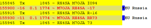
A live example of a QSO is as shown in this image:
Setting Up – Hardware and Software Requirements
Time Sync
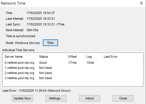
The first thing you need to do is install software to sync your computer’s time as closely as possible with the current time. This is very important for FT8/FT4 as it relies on both stations using the same, accurate time. This is because the time slots of 15 seconds need to begin and end at the same time. My favourite service for this is NetTime (link opens in new tab).
Sound Card
In order to connect your radio to the computer for the purposes of FT8/FT4 decoding and transmission, you need a sound card. Some radios (such as the Yaesu 991 which I use) have a sound card built in. Search on Google for your radio manufacturers website and it will list if your radio has a built in sound card. If not, you can use the sound card in your computer via a TNC (Terminal Node Controller). In the past, you needed to have an (expensive) external TNC to connect your radio to the computer. However, computers now have a sound card built in and you can use this instead. Software such as Direwolf (link opens in new tab) can do this for you. Follow the setup instructions on the website.
Drivers
The next thing you need to setup is the drivers for your computer. Each radio and manufacturer has a different driver. The easiest way to find it is to Google “Virtual COM port driver” and then the name of your radio and your operating system (Windows, Linux, etc.). Make sure you only download these from the official website of the manufacturer, or from a trusted amateur radio specific website. Follow their installation instructions.
Hardware Connection
The final “piece of the puzzle” in terms of hardware is a physical connection between your radio and your computer. Again, each radio has a different type of port to facilitate this. However, most of the modern “shack in the box” radios such as the Yaesu 991/991A use a standard “printer cable” such as THIS (link opens in new tab). However, check on your manufacturer’s website to make sure you are buying the right connecting cable for your radio.
Software
When it comes to digital radio, there are several pieces of software available. However, the most prominent are the widely used WSJT-X (link opens in new tab) and JTDX. Personally, I find that JTDX is easier to setup, but it is down to personal preference and your particular radio. In this article, I will discuss how to configure JTDX, but there are a wealth of tutorials and guides online on how to setup WSJT-X if you find JTDX doesn’t meet your preferences.
Configuring JTDX
As every radio is different and will require different settings both in the radio and in the software, I am unable to give specific details about setting up your radio with JTDX. However, if you search online for “JTDX setup” and the name of your radio, you will find a tutorial on how to do this. In this article, I will be going over the operating basics of JTDX and how to use the software itself.
The next section of this guide will assume you have successfully configured the Settings of your radio and JTDX and a connection has been successfully established between your radio PTT and the software. You can test this by pressing the “TUNE” button on the right side of the main screen (please make sure your radio is tuned on the frequency first). A carrier signal will be transmitted, and you can check your SWR and PO (power) meter on the radio to ensure that the software can successfully access your radio and enable a transmission.
JTDX – The Basics
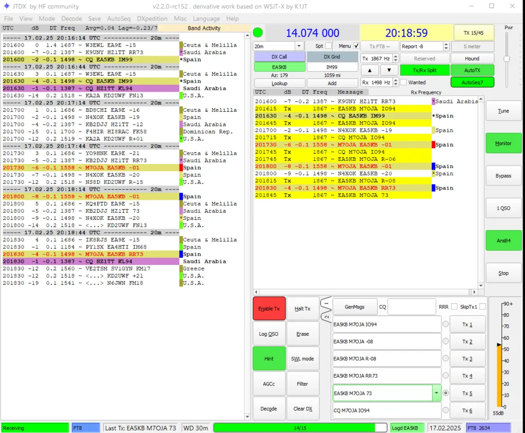
The above image is a screenshot of the main page of JTDX in FT8 mode. The left hand side are all of the live decodes. Each divider with a time and date represents a 15 second transmission slot. There are two slots per minute, either TX 00/30 (meaning per minute you transmit at 00 seconds and 30 seconds) or TX 15/45 (meaning you transmit at 15 seconds and 30 seconds). The right hand side shows only the decodes relevant to you. This includes your transmissions, your selected DX transmissions and anyone transmitting within 10Hz of your signal (more on this later).

- Enable TX– This button enables your transmission. Depending on your selected TX/RX window (00/30 or 15/45), this may begin your transmission immediately, or it will wait until the end of that receive period before transmitting.
- Halt TX – This button stops your transmission immediately.
- Log QSO – If you press this button at the end of a full QSO, a window will appear with the QSO details. You can log this manually, although later in the guide I will explain how to log automatically via your logging software.
- Erase – Clicking this button once will erase all of the decodes (on the left hand side) and clicking twice will erase all of the decodes on the left AND right side.
- Hint – This allows the software to use additional decoders to potentially increase successful decodes of weaker signals. I tend to have this ON.
- SWL Mode – This increases decodes for Shortwave Listeners. Turn this OFF.
- AGCc – This enhances the decode efficiency only if your radio has a similar setting. I have this OFF.
- Filter – This turns on any pre-set filters in the system software (for example, only showing stations from a certain continent). I have this OFF.
- Decode – Clicking this initiates a manual decode. Your software will automatically decode at the end of the receiving period, although occasionally when switching bands you may need to click this at the end of the first receiving period.
- Clear DX – This clears the station you are currently working.
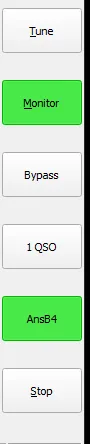
- Tune – This button will transmit a constant tone to your radio. Useful for adjusting the transmission power and balancing the PO and ALC on your radio (more on this later).
- Monitor – This will be green during a receiving period and off (white) during a transmission period. If it is off all of the time, then click to turn it on.
- Bypass – This is a feature used to bypass any text filters you have. Ignore this for now.
- 1 QSO – This is used to turn off transmission after one full QSO. If you are going to set the software up to log automatically (later in the article) then turn this OFF as it will automatically stop transmitting after one QSO.
- AnsB4 – This option will allow the software to reply to stations calling you who you have already worked before. If this is off, it will only reply to new stations. I have this ON.
- Stop – This stops the monitoring and decoding of incoming signals. Make sure this is OFF.
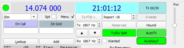
- Band(showing above as 20m) – This allows you to change band within the software. Ensure that your Tx is turned OFF before you change bands, and ensure you tune your radio to the new frequency before transmitting. NOTE that some bands have multiple frequencies listed in the drop down menu. Select the one with a star (*) next to it for the correct (most commonly used) frequency.
- DX Call – If you double click on a station to call them or a station replies to your CQ, their call will show in the box below. You can also click on the purple “DX Call” to manually spot the station.
- DX Grid – As above, when in QSO the DX station’s grid will display in the box below. Tx/Rx (showing above as 1867Hz)- This changes the precise frequency you are transmitting on. If two stations are transmitting within 10Hz of each other, their transmissions will show up on the right hand side. This is useful in the case of calling a station (where the software will automatically change your Rx frequency), however if two stations NOT in QSO are too close, they will cause QSB and their irrelevant messages will show in the right side of the software. You can use the waterfall which opens along with the main window to see a clear frequency, or change to a random number and listen to see if anyone else is using it. You can use the up and down arrows to change both fields.
- AutoTx– This enables/disables the auto sequencing which can be customised. More on this later. Power Slider (top right) – This adjusts the power of the digital transmission. In short, you need to balance it so that the ALC meter on your radio is at zero (or as close to zero as possible) and the PO (output power) on your radio is as close to your transmitting power as possible. To give an example, my radio is set to transmit on 25w. In the example above, my radio was transmitting around 24w and the ALC meter on my radio during transmission was showing as 0. This is a perfect setup. If your power meter (PO) is too low, you will not be transmitting at your desired output power. If the ALC is too high, then your digital signal will be overmodulated and harder for the DX station to decode. You need a balance between the two, and it takes trial and error. My usual strategy is to click the TUNE button to output a carrier signal, set the slider to zero, monitor the PO (power meter) and slowly increase it until the power is 1-2w below my desired transmit power (25w). I then check the ALC, and providing it is zero, then I am ready to go.
Changing from FT8 to FT4
You can change from FT8 to FT4 or another digital mode (although the others are rarely used outside of specific-mode contests) by selecting the relevant option under the “Mode” tab on the top bar of the main page. Ensure that you adjust the POand ALC settings on your radio again as the transmitting power on FT4 will change back to the default. As a rule, whenever you change band, mode or both, you should find the ALC/PO balance again.
NOTE: When changing bands and modes, don’t forget to tune your radio on the new frequency. You can whistle or click the TUNE button to ensure the SWR remains low.
Auto Sequencing
Within JTDX, you can configure the software to automatically choose the best station to call based on certain rules. Screenshots of my setup are below:
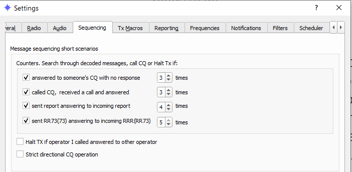
In the image above, the software will apply the following rules automatically:
- Answered to someone’s CQ with no response – 3 times: If you double click on a call in the left side of the JTDX screen (to call a station), the software will send a maximum of 3 messages before it will automatically return to calling CQ.
- Called CQ, received a call and answered – 3 times: If you call CQ, someone replies to you, the software will send a maximum of 3 messages before automatically returning to calling CQ.
- Sent report answering to incoming report – 4 times: This will, upon receiving a signal report, send a maximum of 4 return signal report messages before automatically returning to calling CQ.
- Sent RR73(73) answering to incoming RRR(RR73) – 5 times: This will, upon receiving a RR73/73 message, send a maximum of 5 RR73/73 messages in return until the software automatically begins calling CQ again. Please note that on occasion a station will not hear your final “73” and keep sending “RR73” messages for a number of times. Even if the QSB means they are unable to receive your final message, as long as they send RR73 (and automatically log their QSOs), it will already be in their log. You do not, therefore, need to keep sending several “73” messages and you can log the contact (if not already done automatically) and manually click to call CQ).
NOTE: JTDX is designed to stop “bot” operation where the software makes an indefinite number of QSOs without human intervention. Instead, at the end of a QSO (when receiving or sending a final “73”, the software will disable TX. You need to manually click “Enable TX” to resume contact.

In the image above, the software will automatically find a station to call in this order:
- If multiple stations call you in response to your “CQ”, it will prioritise stations from a new ITU zone, CQ zone or DXCC.
- If there are none of the above, it will prioritise new band/mode stations. For example, if two German stations and one Albanian station call you on 20m (and you have already worked Germany but not Albania), the software will reply to Albania as it is a new country on that particular mode and band.
- If only one station calls you, it will reply to that station. If no stations reply to you, or you haven’t yet called CQ, it will search through the decoded messages (on the left side) and choose a station from a new ITU zone, CQ zone or DXCC.
- If there are none of the above, then it will choose the station with the best Signal to Noise Ratio (SNR). This will be the station with the highest number (ranging from -25 to +25).
- If there are no stations to reply to, then it will automatically call CQ.
Please note in the above image, I have “Answer worked B4 calls” enabled. This means that it will not ignore stations that you have worked previously on that band/mode. You can also turn this on/off with the “AnsB4” in the right hand menu on the main page.
Please note also, “Report Message Priority” is enabled in the image above. This means that if you receive two or more calls, it will prioritise the call giving you a signal report. For example, if M6XXX sends you an initial call (M7OJA M6XXX IO84) and DL2XXX sends you a signal report (M7OJA DL2XXX -12), the software will prioritise the DL2XXX station as they are further in the QSO than the other station. I would strongly recommend enabling this setting.
Reporting
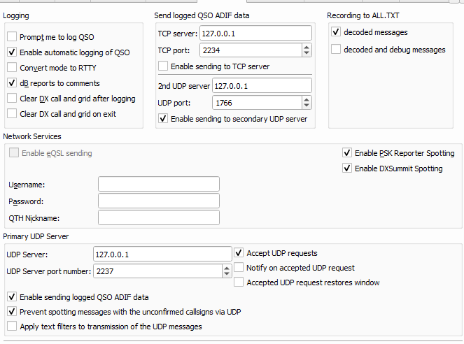
In the Settings -> Reporting tab, make sure you enable “Enable PSKreporter spotting” and “Enable DXSummit Spotting”. This will mean that, upon hearing a station (even if they aren’t in QSO with you), your computer will upload a “spot” to show on the PSKReporter website.
Integrating JTDX with Digital Logging
JTDX has the ability to communicate with other programs on your computer via the UDP protocol. This means that the logging software running on your computer (such as Log4OM or Ham Radio Deluxe, for example) can receive messages from JTDX and QSOs can automatically be logged.
Digital Logging
If you have not already setup digital logging on your computer, it is well worth doing so. You can automatically upload QSO data to confirmation websites (such as QRZ.com, eQSL, LoTW, Clublog, etc.), track award progress, view solar information and propagation reports, easily search your QSOs, prepare QSL labels and view instructions, view live station information/operator details for stations you are in QSO with and track previously worked stations. All of this is provided in the free Log4OM V2 software. You can download the software HERE (link opens in new tab).
I have a useful guide on this website to tell you everything you need to know about digital logging and how to setup powerful features within the Log4OM suite. You can view the guide HERE(link opens in new tab).
Configuring Automatic Digital Logging
Within the settings page of JTDX, you can specify the UDP port that the software will broadcast messages on. Within your logging software Settings page, configure it to receive UDP messages on the same port that JTDX uses. This means that as soon as you receive a RR73/73 message, the logging software will pick it up and add it to your log. You can also specify that your logging software updated QSO info (meaning it fetches the station name/address from QRZ.com) and you can specify for electronic confirmations to be sent (meaning that as soon as it enters your log automatically, it will be uploaded to QRZ.com, eQSL, LoTW, etc.). This may sound a bit complicated at first until you become familiar with JTDX and your logging software suite. You can skip this step for now and manually log your FT8/FT4 contacts until you become more experienced with the software.
QSLing with Digital Modes
Within digital modes, sending a QSL is just as common as with a SSB or CW QSO. Digital confirmations such as QRZ.com, LoTW and eQSL are extremely popular and count towards awards. Sending paper QSL cards are also common for digital modes, as it is easier to make a DX QSO and therefore may be the first contact someone has had with a particular country/DXCC.
If you are interested in learning about QSL cards and how to send them, you can check out my Ultimate Guide to QSLing HERE (link opens in new tab).
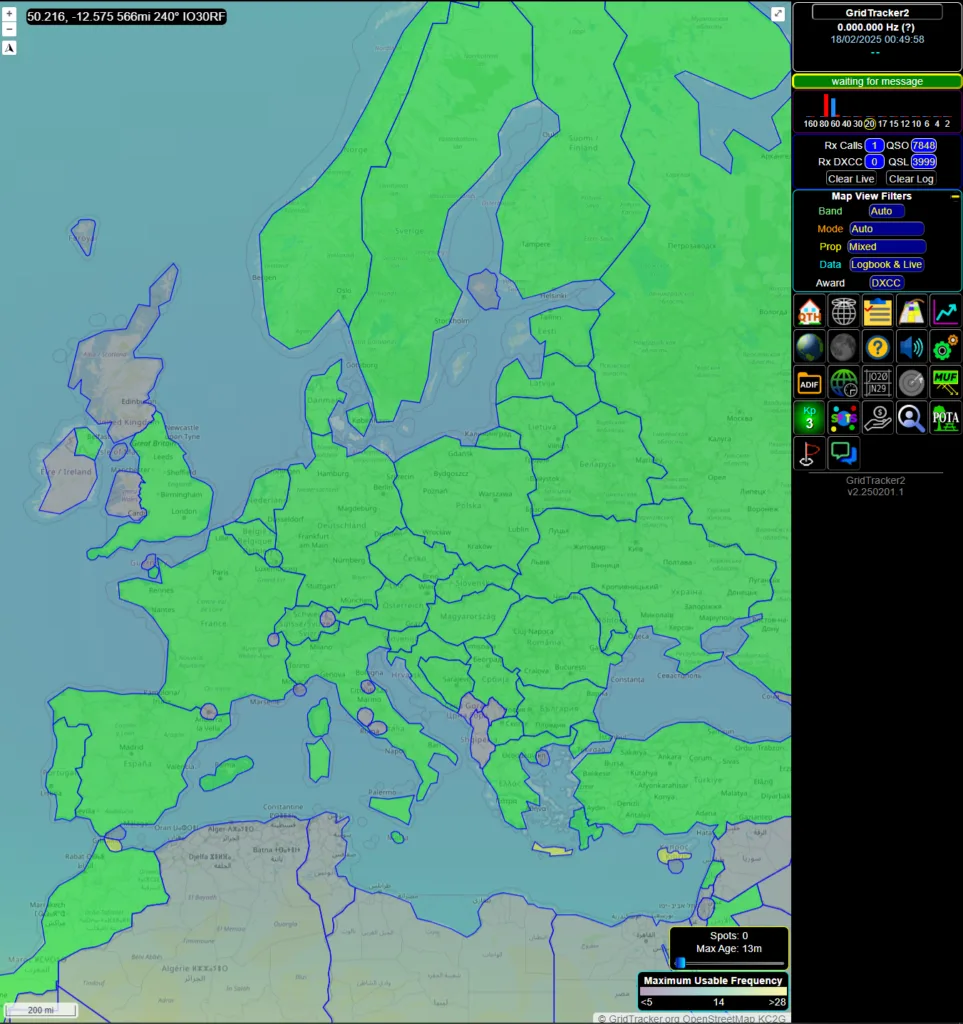
Basics of Gridtracker
Gridtracker is software designed to enhance the FT8/FT4 experience and runs adjacent to JTDX. It provides a useful map showing the PSKReporter spots on that band/mode, a call roster showing all of the calls decoded within JTDX, a grid map to show worked grid squares and DXCCs, a live chat function allowing you to make a station aware that you are calling them, an automatic callsign lookup from QRZ.com so you can see who you are calling and live POTA lookup (to compare your JTDX decodes with the POTA cluster and fetch park reference numbers), among many other handy features.
You can download Gridtracker on their website HERE (link opens in a new tab).
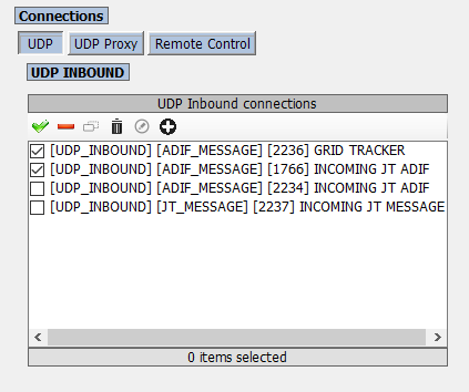
Gridtracker also requires a UDP port setup. For this, you can use the “Secondary UDP Server” function within the JTDX menu (JTDX -> Settings -> Reporting). Ensure that this port is the same as within the settings of Gridtracker.
Summary
Hopefully, if you are here at the end, you have successfully made a QSO on FT8 or FT4. If not, don’t give up hope. It took me several years to completely come to terms with the complexity of digital modes, and I am still learning new things to try to this day. Keep going, and be sure to ask questions in Facebook groups (or you can contact me via the Contact Form (link opens in new tab) and consult online resources specific to your radio and setup.
Beyond FT8 and FT4, there are many other digital modes to experiment with. You can have a look on the HF Contest Calendar (link opens in new tab) to see any mode-specific contests. Within these contests, activity is increased on a particular mode giving you the chance to try to make a QSO.
I hope you have found this resource useful, and as always, feel free to share this within your Facebook groups and to any fellow operators who may like to try digital modes.
2 responses to “FT8 – All You Need To Know”
-
Do you have 5 min for a FaceTime to k1te@lupton.us at your convenience in the next week? Boston time? Your timing and my stem project direction today along the 1914 Marconi Marion Chatham path are spooky timing.
-
Hello, sure, drop me an email at oscar@m7oja.com with info and we can arrange it.
73 de M7OJA
-
Leave a Reply